Title here
Summary here
April 29, 2013 in Systems7 minutes
In preparation for an upcoming post, I was reminded about a commonly referred to feature in most IGPs - the concept of Equal-Cost Multipath, or simply ECMP. This is the idea that multiple routes with the same cost to a remote network should get placed in the routing table alongside each other and packets should load-balance over them to use the additional available paths. After all, it’s the same cost, so why not?
ECMP isn’t really talked about with EIGRP, since the metric is more complicated and routes with equal metric rarely happen, even if they are physically similar. This is a big reason why EIGRP provides a variance parameter, allowing you to define a metric that is “good enough” to be viewed as equal and able to be load-balanced on.
Due to a specific failure I will be going over in a future post, I was forced to think about exactly what type of load balancing was used. In my CCNA/CCNP studies I was led to believe this was simply round-robin - each packet gets a new link, so they’re all used equally. But is this actually the case?
I put this GNS3 topology together so we could explore the way that changes to an example OSPF topology will influence the routing table, and more specifically, point out how the default multipathing features in a Cisco router will impact our traffic flow during reconvergence:
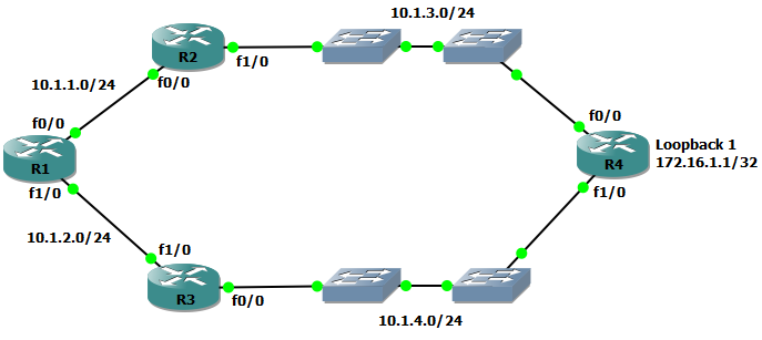
The goal is to cause certain failures within the environment and observe the impact to traffic destined from R1 to the loopback address of 172.16.1.1, advertised from R4 over two equal-cost paths. I put two switches in between the R2/R3 pair and R4 so that I could break connectivity between these routers without causing link-down events (I’ll just delete the link between the switches). The reason for avoiding link-down events for this post is that OSPF routers that detect a link failure on an interface will typically originate a new Router LSA for itself that leaves out the corresponding transit network:
  LS age: 1205
  Options: (No TOS-capability, DC)
  LS Type: Router Links
  Link State ID: 172.16.1.1
  Advertising Router: 172.16.1.1
  LS Seq Number: 80000009
  Checksum: 0x3365
  Length: 60
  Number of Links: 3

    Link connected to: a Stub Network
     (Link ID) Network/subnet number: 172.16.1.1
     (Link Data) Network Mask: 255.255.255.255
      Number of TOS metrics: 0
       TOS 0 Metrics: 1

    Link connected to: a Transit Network
     (Link ID) Designated Router address: 10.1.4.4
     (Link Data) Router Interface address: 10.1.4.4
      Number of TOS metrics: 0
       TOS 0 Metrics: 1

    Link connected to: a Stub Network
     (Link ID) Network/subnet number: 10.1.3.0
     (Link Data) Network Mask: 255.255.255.0
      Number of TOS metrics: 0
       TOS 0 Metrics: 1
This LSA lists the 10.1.3.0 network as a stub network, whereas it would normally be a transit network if there was connectivity to another subnet. This LSA would make it’s way back to R1 within a few seconds, meaning the network would reconverge on the working link quickly. So I’m using switches in this topology to help me cause indirect failures.
“Why all these extra steps to produce more downtime?” you say. It’s true, most point-to-point connections between two routers don’t involve a few dumb switches. However, with the advent of virtual routing, the likelihood of failures not causing link-down events is actually significantly higher. This is a way for me to simulate this behavior in GNS3.
So, while the quick reconvergence that this provides is nice, but the cause doesn’t properly show the behavior that might be produced in a virtual routing environment, where failures may not cause link-down events, which would normally cause relatively quick reconvergence. The normal routing table on R1 (all links and OSPF neighbor relationships up) is as expected:
R1#show ip route ospf
     172.16.0.0/32 is subnetted, 1 subnets
O       172.16.1.1 [110/3] via 10.1.2.3, 00:29:28, FastEthernet1/0
                   [110/3] via 10.1.1.2, 00:29:28, FastEthernet0/0
     10.0.0.0/24 is subnetted, 4 subnets
O       10.1.3.0 [110/2] via 10.1.1.2, 00:29:28, FastEthernet0/0
O       10.1.4.0 [110/2] via 10.1.2.3, 00:29:28, FastEthernet1/0
Take a look at the LSA shown above. Normally both transit networks would be contained there and produce the routing table shown right above. When I delete the link in between the two switches that provide connectivity between R2 and R4, a large amount of downtime is experienced - roughly 40 seconds or more of dropped packets.
R1#ping 172.16.1.1 repeat 100000

Type escape sequence to abort.
Sending 100000, 100-byte ICMP Echos to 172.16.1.1, timeout is 2 seconds:
!!!!!!!!!!!!!!!!!!!!!!!!!!!!!!!!!!!!!!!!!!!!!!!!!!!!!!!!!!!!!!!!!!!!!!
!!!!!!!!!!!!!!!!!!!!!!!!!!!!!!!!!!!!!!!!!!!!!!!!!!!!!!!!!!!!!!!!!!!!!!
!!!!!!!!!!!!!!!!!!!!!!!!!!!!!!!!!!!!!!!!!!!!!!!!!!!!!!!!!!!!!!!!!!!!!!
!!!!!!!!!!!!!!!!!!!!!!!!....................!!!!!!!!!!!!!!!!!!!!!!!!!!
!!!!!!!!!!!!!!!!!!!!!!!!!!!!!!!!!!!!!!!!!!!!!!!!!!!!!!!!!!!!!!!!!!!!!!
Success rate is 94 percent (380/401), round-trip min/avg/max = 16/40/76 ms
This is a worst-case scenario. Like I mentioned before, if you have redundant paths in a physical network, a link-down event will usually cause OSPF to send out new LSAs right away, causing only a few pings to get dropped. However, we have two paths in the routing table already! Why wouldn’t we just use the working redundant path? Or worst case scenario, why wouldn’t we just drop every other ping, since we’re load balancing?
I’m belaboring the point a little bit but only because the current introductory to moderate-level curricula regarding routing, especially in Cisco circles create the assumption that load-balancing is just round robin, when in reality it’s not, and I want to be clear on the details concerning this problem. Let’s first identify why we have the 40+ second downtime. This is the amount of time it takes for an OSPF neighbor to get recognized as “down” (Dead timer). What this means is that the reconvergence that takes place will only happen after the OSPF neighbor is viewed as “down”, which is when those LSAs will get aged out. However, this would imply that the router is ONLY using that particular route (and not the equal cost path). So how exactly is ECMP load balancing?
Keep in mind - the role of an IGP doesn’t really include load balancing. OSPF will learn link-states, feed them to the Djikstra algorithm, and the routes will get placed into the RIB as a result. It is up to the routing protocol to place routes into the routing table based on the decision points specific to each protocol. Sometimes this means that multiple routes will get placed, because features like ECMP are pretty common in most routing protocols.Then, the vendor’s implementation of the RIB will make decisions based on their own specific implementations.
There are a few IETF documents that discuss L3 load balancing, such as RFC 2991 - Multipath Issues in Multicast and Unicast Next-Hop Selection or RFC 2992 - Analysis of an Equal Cost Multipath Algorithm. This are generally accepted informational analyses (not standards) that talk a little bit about how these tasks are commonly accomplished, but they are not standards that vendors must follow. IGPs like OSPF are standards-based but the standards can’t dictate how each vendor utilizes the data that these protocols provide.
In Cisco, load balancing on an L3 basis is very closely tied to hardware forwarding, like Route Caching and Cisco Express Forwarding. The explanatory article on Cisco’s site called “How does load balancing work?” makes it pretty clear how Cisco platforms do it. Packets that require process switching are load balanced in a much more round-robin style, whereas routing done via hardware like in IP CEF will take the approach of load balancing “flows” of traffic, rather than packets, which in this case is just identified as per-destination. Very similar to a port-channel, there’s a property in each packet (destination IP address) that is used to identify which link should be used, and if that property does not change, then the other link is not used. Nothing we’re not used to thinking about in a typical 802.3ad scenario.
Don’t just take my word for it. Try disabling all forms of fast switching (CEF and otherwise) on a Cisco router and/or it’s relevant interfaces - you get this wonky behavior (I again disconnect the link in the middle of the ping to simulate a failure):
R1(config)#no ip cef
R1(config)#int range Fa0/0 , Fa1/0
R1(config-if)#no ip route-cache cef
R1(config-if)#no ip route-cache
R1(config-if)#end
R1#ping 172.16.1.1 rep 10000
Type escape sequence to abort.
Sending 10000, 100-byte ICMP Echos to 172.16.1.1, timeout is 2 seconds:
!!!!!!!!!!!!!!!!!!!!!!!!!!!!!!!!!!!!!!!!!!!!!!!!!!!!!!!!!!!!!!!!!!!!!!
!!!!!!!!!!!!!!!!!!!!!!!!!!!!!!!!!!!!!!!!!!!!!!!!!!!!!!!!!!!!!!!!!!!!!!
!!!!!!!!!!!!!!!!!!!!!!!!!!!!!!!!!!!!!!!!!!!!.!.!.!.!.!.!.!.!.!.!.!.!.!
.!.!.!.!.!.!.!.!!!!!!!!!!!!!!!!!!!!!!!!!!!!!!!!!!!!!!!!!!!!!!!!!!!!.
Success rate is 92 percent (256/278), round-trip min/avg/max = 8/39/72 ms
R1#
Here, it’s obvious that there is pure round-robin style load balancing - when the failure occurs from me disconnecting a link, every other packet gets dropped while OSPF reconverges.
The routing protocols may be standards-based, but the implementation of the RIB (or FIB) is up to the vendor. Load balancing is influenced by the routing protocol, but it is performed by the forwarding plane, so the rules may be different between vendor platforms. Kudos to Cisco on this one for providing a document that clearly states why the load balancing operates the way that it does, and for making that document easy to find with a basic Google search.