Title here
Summary here
August 22, 2012 in Systems7 minutes
I ran into an issue that presented itself two different ways, each at a different customer. I posted a while back about a customer that wanted to use only a single Nexus 5000, since that was all that was available. I wanted to bundle all four CNA ports on the Netapp storage array to the Netapp SAN. However, after I created this port channel and bound the virtual fibre channel (VFC) interface to it, the VFC interface would not come up.
The Cisco Nexus 5000 will, for each of its virtual fibre channel (VFC) interfaces, run FCoE traffic over no more than a single physical interface.
Direct connect FCoE (that is, a direct connect to CNAs through a bind interface) is not supported on a port channel of a Nexus 5000 Series or fabric extender interface if it is configured to have more than one interface. Direct connect FCoE is supported on port channels with a single link to allow for FCoE from a CNA connected through a vPC with one 10GB link to each upstream switch/fabric extender
– Cisco Nexus 5000 Series NX-OS FCoE Configuration Guide for NX-OS 6.x
This limitation exists at least through NX-OS 6.x. Interestingly enough, the standard guide for FCoE on the Nexus 5500 (not NX-OS version-dependent) doesn’t mention this limitation. You’ll have to go to a guide for a specific NX-OS version to read it (Cisco, you might want to change this, as it can be misleading)
This does not seem to apply to Inter-Switch Links (ISL), only VF_Ports that connect downstream to VN_Ports. I haven’t found documentation that makes this super clear, so if you have anything, feel free to post in the comments and I’ll update.
In the simplest sense, this can be a single ethernet interface, connected directly to the CNA port on the storage array:

You can also configure this in a Virtual Port Channel (VPC) design. In this scenario, each switch has VFC interfaces bound to a port-channel interface - each of which represents one leg of a VPC.

This is a little confusing - the aforementioned limitation would normally prevent us from doing this, as a port-channel interface could have more than one physical member. However, in a VPC design , the port channel interfaces can (and often do) only have one physical port as a member, so this limitation is often not encountered.
My first customer only had a single Nexus switch, so I wanted to establish a port channel between the single Nexus switch and the Netapp filers. Since this would require me to bind the VFC interface to a port channel with more than a single member, this was not an acceptable configuration, and the VFCs did not come up as a result:
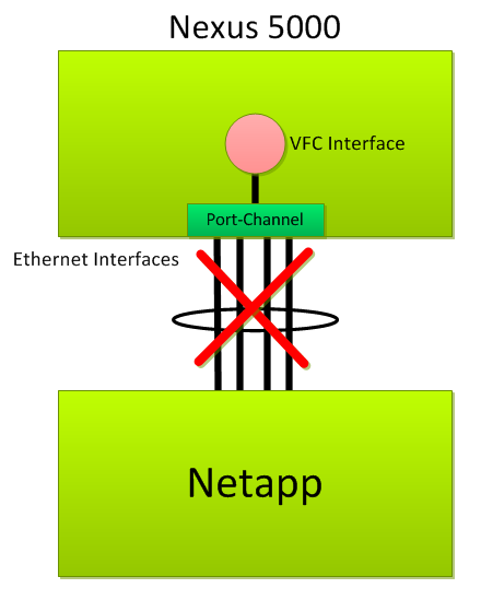
This is NOT a supported configuration. It’s important, though, to realize that the problem isn’t with the mere fact that the VFC interface is bound directly to a port-channel interface. If that wasn’t allowed, we wouldn’t be able to run FCoE over a VPC design. The problem is that in this configuration, the port-channel interface to which the VFC is bound contains multiple participating ethernet interfaces.
I then ran into a similar issue this week where I considered running multiple interfaces from each Nexus 5000, but in a VPC. For the same reason, this was also not supported.
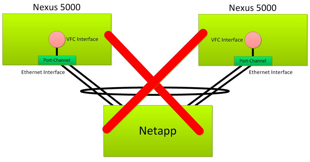
Again, having the VFC’s bound to a port channel is perfectly fine. The problem was that the port channels had more than one participating member.
Also, all of the topologies shown above are perfectly acceptable - when you’re not running FCoE.
As I said, this is a restriction on FCoE only, since the problem occurs when the VFC interfaces are bound to a port channel with multiple active ports. If you’re not planning on running FCoE over the physical topologies shown above, you won’t have a problem - all of this works just fine from a pure Ethernet and virtual port channel perspective. In fact, the last diagram is a very common method of connecting to UCS Fabric Interconnects - these usually have high bandwidth/redundancy requirements. However, with respect to downstream connections to an FCoE SAN, you’re limited to one cable per switch if you want to bind the VFCs to the port channels.
So you may say “Why Matt - I am not simply content with running a single cable from each Nexus switch - I have 4/8/N CNA ports in the back of my storage array - how can I take advantage of each and every one?”
I’d like to go through a few options if this is your need, so if you don’t want to get down in the weeds, or don’t mind sacrificing a few ports to keep things simple, stop reading here.
(The following is geared towards a Netapp FAS-Series array with the UTP cards installed for FCoE, but can really be applied to any FCoE-capable array when you want to maximize the use of available converged network adapters, as long as that array supports LACP)
There are a few ways to design the storage/data network to get around this limitation. First, you could dedicate two of the CNA’s for IP storage traffic, and use the other two for Fibre Channel. This isn’t pretty, as it’s purely a manual form of load-sharing, but it’s a viable solution.
(Note that the VFCs are still bound to the port-channel interface, not directly to the ethernet interface, depicted by the fact that the VFCs are “inside” the switch in the diagram)

I’ll spoil the fun and just tell you: I don’t like this configuration - and it shouldn’t be much of a surprise. You’re essentially taking the value out of having converged network adapters in the first place. If you wanted to do this, why not just run Fibre Channel on dedicated FC ports, and use dedicated ethernet ports for IP-based storage traffic? You can do it if you want, but I won’t.
Alternatively, you could make both Fibre Channel and IP-based storage traffic available via each and every interface:
Here, I’m utilizing all four ports for any kind of storage traffic on the network. I could even include CIFS or iSCSI on this if I really wanted to - I’m taking advantage of the fact that these ports can run it all. In addition, I have full redundancy. This is still a little clunky, but a much better option than before. FC multipathing will take care of utilizing all of the links possible in this scenario, and for IP-based storage, some load balancing functionality on the client could be used to make best use of the available bandwidth.
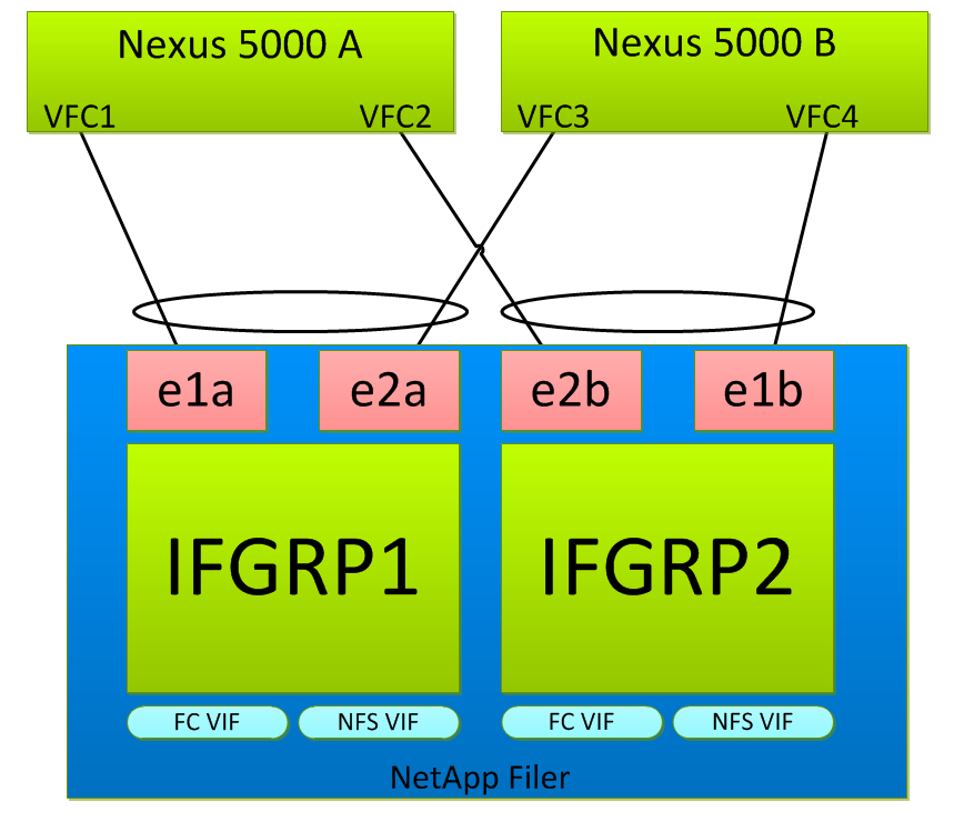
Want to step into dream land? Unfortunately, the following design is unsupported (and I’ll explain why), but here’s how I’d like to do it: Bundle all four ports together on the storage array so that you have a single VIF for each protocol, and all four CNA ports are participating in a glorious 40GB VPC.

Note that I’ve moved the VFC interfaces outside of the boxes representing the Nexus switches. This is because in this configuration, you would have to bind each VFC directly to each individual ethernet interface. I could then provision VIFs off of this single ifgrp for each storage protocol, which is more simple.
This looks nice on paper, but unfortunately, the Nexus 5000s will not allow the VFC interfaces to come up if they are bound to ethernet interfaces that are members of a port channel. Maybe Cisco will enable this behavior down the road, but right now, not so much.
So for now, option #2 seems to be the best. Each VPC will be limited to 10G per switch connection for the time being, and you’ll have to perform some manual load balancing between the two NFS VIFs that are created as a result of duplicating the VLAN availability on both Netapp ifgrps.
Thanks to Chris over at www.cknetworx.net and Twitter @ck_nic for helping me iron out some of the “technical wrinkles”.