Title here
Summary here
February 13, 2013 in Systems11 minutes
For so long, I’ve heard - as have many of you I’m sure - that GNS3, though a GREAT emulator for Cisco IOS software, is not practical for studying anything related to switching. Routing is handled just fine, but because of the proprietary ASICs in Cisco switches, it is not something that can be easily reverse-engineered, thus GNS3 cannot do it. After all, all routing is essentially done in software in GNS3.
I actually wrote this article in part over a year and a half ago, but these concepts still hold up, and I decided to get it out of drafts and publish because I still believe it’s useful to those looking to get into this industry but don’t have real equipment to play with, as is most often the case.
I’d like to point out a very reasonable solution to this problem. Keep in mind that this will not be the same as having actual switches, because some of the syntax can be quite different, but if you’re vigilant, you’ll be able to interpolate between the syntax shown, and what you can expect on a real switch. These explorations will help a CCNA - and even CCNP - candidate get ready for the concepts they’ll be faced with on the exam.
You’ll notice that you have an “EtherSwitch Router” over to the left on your toolbar. This needs a c3700 image to run, and I selected the following:
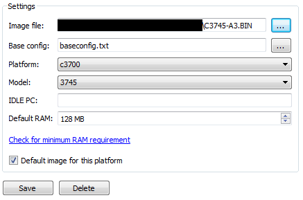
Now that there’s an image selected, don’t forget to set an IDLE PC value, as you should with every platform in GNS3 so that your environment can run smoothly. There are walkthroughs all over the web on how to do this.
My main point in writing this article is to get some switches powered on and show you how to do some basic switching tasks on this platform. For that, we need to see a topology. I have thrown this lab together in GNS3:
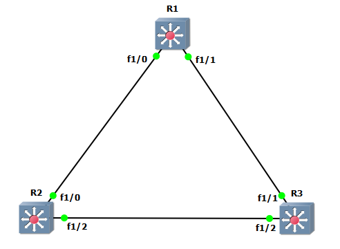
You may need to enable “Always use manual mode when adding links” under Preferences » General » GUI Settings to pick these specific interfaces.
The first thing you need to do to get familiar with what’s going on here, is show the interfaces available:
R1#show ip int br
Interface                  IP-Address      OK? Method Status                Protocol
FastEthernet0/0            unassigned      YES unset  administratively down down
FastEthernet0/1            unassigned      YES unset  administratively down down
FastEthernet1/0            unassigned      YES unset  administratively down down
FastEthernet1/1            unassigned      YES unset  administratively down down
FastEthernet1/2            unassigned      YES unset  administratively down down
FastEthernet1/3            unassigned      YES unset  administratively down down
FastEthernet1/4            unassigned      YES unset  administratively down down
FastEthernet1/5            unassigned      YES unset  administratively down down
FastEthernet1/6            unassigned      YES unset  administratively down down
FastEthernet1/7            unassigned      YES unset  administratively down down
FastEthernet1/8            unassigned      YES unset  administratively down down
FastEthernet1/9            unassigned      YES unset  administratively down down
FastEthernet1/10           unassigned      YES unset  administratively down down
FastEthernet1/11           unassigned      YES unset  administratively down down
FastEthernet1/12           unassigned      YES unset  administratively down down
FastEthernet1/13           unassigned      YES unset  administratively down down
FastEthernet1/14           unassigned      YES unset  administratively down down
FastEthernet1/15           unassigned      YES unset  administratively down down
Vlan1                      unassigned      YES unset  administratively down down
You notice that there’s 16 interfaces in card 1. These 16 interfaces represent our NM-16ESW module, and is what allows us to perform our switching labs. We will be working with these interfaces (Fa1/0 - 15) to perform switching. The two ports in card 0 (Fa0/*) are not capable of L2, so you cannot make them into switchports.
However, this is still a router and should be treated as such until we sort of….make it a switch. To do that, we enable each interface and make them switchports:
R1#conf t
R1(config)#interface range Fa1/0 - 15
R1(config-if-range)#no shutdown
R1(config-if-range)#switchport
These ports are now active, and are switchports, that is, they now operate at layer 2 rather than layer 3. These devices are now basically Layer 3 switches.
Now that we have functional switches, lets dig into some common switching concepts and see how much we’re able to play with in GNS3:
Spanning Tree is pretty easy. Once switching has been enabled as shown above on all devices, spanning tree operates exactly like one who is familiar with it would expect. The devices run traditional PVST by default, as is made evident by the output of the following:
R1#show spanning-tree brief

VLAN1
  Spanning tree enabled protocol ieee
  Root ID    Priority    32768
             Address     c400.034c.0000
             This bridge is the root
             Hello Time   2 sec  Max Age 20 sec  Forward Delay 15 sec

  Bridge ID  Priority    32768
             Address     c400.034c.0000
             Hello Time   2 sec  Max Age 20 sec  Forward Delay 15 sec
             Aging Time 0

Interface                                   Designated
Name                 Port ID Prio Cost  Sts Cost  Bridge ID            Port ID
-------------------- ------- ---- ----- --- ----- -------------------- -------
FastEthernet1/0      128.41   128    19 FWD     0 32768 c400.034c.0000 128.41
FastEthernet1/1      128.42   128    19 FWD     0 32768 c400.034c.0000 128.42
This shows the spanning-tree information for VLAN 1. There are also vlan-specific spanning-tree configuration commands. What I don’t see, however, is any indication of rapid PVST, or even a way to configure it.
R1(config)#spanning-tree ?
  backbonefast  Enable BackboneFast Feature
  portfast      Spanning tree portfast options
  uplinkfast    Enable UplinkFast Feature
  vlan          VLAN Switch Spanning Tree

R1(config)#spanning-tree vlan 1 ?
  forward-time  Set the forward delay for the spanning tree
  hello-time    Set the hello interval for the spanning tree
  max-age       Set the max age interval for the spanning tree
  priority      Set the bridge priority for the spanning tree
  root          Configure switch as root
This is because this image does not support RSTP. We now come to a feature that we’re actually unable to lab in GNS3. While this may seem like a downer, I urge you to think about the syntax required for enabling RSTP on traditional switching platforms. Not too difficult, right? Really the only thing RSTP brings from a certification exam perspective is the new port states, which can be studied from a book. If it’s still not enough, this is something you’ll need physical equipment to try.
I don’t view this as a big deal. This DOES allow us to study basic things like port states, STP security features like backbonefast, and the effect of tweaking timers. That’s easily CCNA-level and even CCNP-level concepts.The fact that I can still lab PVST is enough for me, and I don’t feel like I’m missing much not being able to run RSTP. In a real enterprise environment, RSTP is a much preferred option, but since this is just for studying, and since RSTP requires only a single command to configure, we’re not missing much here.
EtherChannel, or “port channel”, is a way of grouping multiple links together for increased bandwidth and redundancy. Let’s see how GNS3 handles this.
R1(config)#int ra Fa1/0 , Fa1/5
R1(config-if-range)#channel-group 1 mode ?
  on  Enable Etherchannel only

R1(config-if-range)#channel-group 1 mode on
Creating a port-channel interface Port-channel1

*Mar  1 01:00:41.707: %EC-5-BUNDLE: Interface Fa1/0 joined port-channel Po1
*Mar  1 01:00:42.395: %EC-5-BUNDLE: Interface Fa1/5 joined port-channel Po1
*Mar  1 01:00:43.651: %LINK-3-UPDOWN: Interface Port-channel1, changed state to up
*Mar  1 01:00:44.651: %LINEPROTO-5-UPDOWN: Line protocol on Interface Port-channel1, changed state to up

R1#show etherchannel summary
Flags:  D - down        P - in port-channel
        I - stand-alone s - suspended
        R - Layer3      S - Layer2
        U - in use
Group Port-channel  Ports
-----+------------+-----------------------------------------------------------
1     Po1(SU)     Fa1/0(P)   Fa1/5(D)
Looks like it can be done, but there’s really not much available for us to do beyond simply statically bundling the ports together. We aren’t given the option to enable LACP or PAGP. We are, however, still able to configure the global setting for the hashing mechanism to load-balance traffic on these port channels:
R1(config)#port-channel load-balance ?
  dst-ip       Dst IP Addr
  dst-mac      Dst Mac Addr
  src-dst-ip   Src XOR Dst IP Addr
  src-dst-mac  Src XOR Dst Mac Addr
  src-ip       Src IP Addr
  src-mac      Src Mac Addr
While this is cool and fun to play with, it doesn’t really have a huge impact on Cisco curriculum, as port-channels are a light subject as it is. Good to know this is possible, though.
Like anyone who has actually run a functional network, I despise VTP, but Cisco has deemed it necessary to keep this “feature” in their curricula for the time being. The configuration for VTP is different than on a traditional Catalyst switch, but the bells and whistles are the same, and you can observe the same behavior.
The VTP configuration is found in the same place as the VLAN configuration - in the old VLAN configuration context, which any modern Cisco switch has since moved away from.
R1#vlan database
R1(vlan)#vtp ?
  client       Set the device to client mode.
  domain       Set the name of the VTP administrative domain.
  password     Set the password for the VTP administrative domain.
  pruning      Set the administrative domain to permit pruning.
  server       Set the device to server mode.
  transparent  Set the device to transparent mode.
  v2-mode      Set the administrative domain to V2 mode.

R1(vlan)#vtp domain cisco
Changing VTP domain name from NULL to cisco
R1(vlan)#vtp password secret
Setting device VLAN database password to secret.
R1(vlan)#vtp server ?

R1(vlan)#vtp server
Device mode already VTP SERVER.
R1(vlan)#vlan 10
VLAN 10 added:
    Name: VLAN0010
R1(vlan)#apply
APPLY completed.
R1(vlan)#exit
R1#show vtp ?
  counters  VTP statistics
  status    VTP domain status

R1#show vtp status
VTP Version                     : 2
Configuration Revision          : 1
Maximum VLANs supported locally : 256
Number of existing VLANs        : 6
VTP Operating Mode              : Server
VTP Domain Name                 : cisco
VTP Pruning Mode                : Disabled
VTP V2 Mode                     : Disabled
VTP Traps Generation            : Disabled
MD5 digest                      : 0x61 0x60 0x65 0xE6 0xC8 0xF3 0x98 0xC6
Configuration last modified by 0.0.0.0 at 3-1-02 01:16:06
Local updater ID is 0.0.0.0 (no valid interface found)
As you can see, the concepts are the same, and if you can interpolate between the subtle configuration differences, you can still use this to study for the exam - just make sure you spend some time in front of a real switch for at least a little bit so you can remember the actual context of the commands the exam will be expecting.
We also configure R3 to be a VTP client and see that it receives the new VLAN database revision.
R3(vlan)#vtp client
Setting device to VTP CLIENT mode.
R3(vlan)#vtp domain cisco
Domain name already set to cisco .
R3(vlan)#vtp password secret
Setting device VLAN database password to secret.

R3#show vtp status
VTP Version                     : 2
Configuration Revision          : 1
Maximum VLANs supported locally : 256
Number of existing VLANs        : 6
VTP Operating Mode              : Client
VTP Domain Name                 : cisco
VTP Pruning Mode                : Disabled
VTP V2 Mode                     : Disabled
VTP Traps Generation            : Disabled
MD5 digest                      : 0x61 0x60 0x65 0xE6 0xC8 0xF3 0x98 0xC6
Configuration last modified by 0.0.0.0 at 3-1-02 01:16:06
R1#show vlan?
vlan-range  vlan-switch  vlans

R3#show vlan-switch

VLAN Name                             Status    Ports
---- -------------------------------- --------- -------------------------------
1    default                          active    Fa1/0, Fa1/3, Fa1/4, Fa1/5
                                                Fa1/6, Fa1/7, Fa1/8, Fa1/9
                                                Fa1/10, Fa1/11, Fa1/12, Fa1/13
                                                Fa1/14, Fa1/15
10   VLAN0010                         active
VLAN 10 made it to R3 with the new configuration revision.
We’re running all of this in GNS3, which is good for practicing Layer 3 stuff, so who would write a blog post on this topic without addressing Layer 3 Switching?
Let’s change up the topology a little bit. I’ve placed R1 as the center of a now-linear network, where R2 must go through R1 to get to R3.
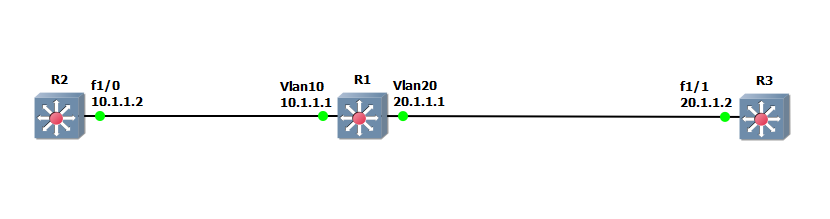
I placed each port on R1 in different VLANs (access), and assign IP addresses to each SVI:
R1(config)#int Fa1/0
R1(config-if)#switchport mode access
*Mar  1 01:41:58.571: %DTP-5-NONTRUNKPORTON: Port Fa1/0 has become non-trunk
R1(config-if)#switchport access vlan 10
R1(config-if)#int Fa1/1
R1(config-if)#switchport mode access
*Mar  1 01:42:46.251: %DTP-5-NONTRUNKPORTON: Port Fa1/1 has become non-trunk
R1(config-if)#switchport access vlan 20
R1(config)#int vlan 10
*Mar  1 01:36:15.775: %LINEPROTO-5-UPDOWN: Line protocol on Interface Vlan10, changed state to up
R1(config-if)#ip addr 10.1.1.1 255.255.255.0
R1(config-if)#int vlan 20
*Mar  1 01:36:38.711: %LINEPROTO-5-UPDOWN: Line protocol on Interface Vlan20, changed state to up
R1(config-if)#ip addr 20.1.1.1 255.255.255.0
With IP addresses assigned, it’s time to do our routing. The device is natively a router, so setting up a quick (and lazy) EIGRP configuration is as I expected, and our neighbors came up.
R1(config)#router eigrp 10
R1(config-router)#no auto
R1(config-router)#network 0.0.0.0 0.0.0.0
R1(config-router)#exit
R1(config)#exit
R1#
*Mar  1 01:47:54.543: %DUAL-5-NBRCHANGE: IP-EIGRP(0) 10: Neighbor 10.1.1.2 (Vlan10) is up: new adjacency
*Mar  1 01:47:54.963: %DUAL-5-NBRCHANGE: IP-EIGRP(0) 10: Neighbor 20.1.1.2 (Vlan20) is up: new adjacency
A quick ping from R2 to R3 shows we’ve got end-to-end connectivity.
R2#ping 20.1.1.2

Type escape sequence to abort.
Sending 5, 100-byte ICMP Echos to 20.1.1.2, timeout is 2 seconds:
!!!!!
Success rate is 100 percent (5/5), round-trip min/avg/max = 40/44/60 ms
In conclusion, we’ve run into a few caveats in dealing with GNS3 for switching labs, but on the whole they are manageable. Do NOT focus on the syntax, refer to real equipment or your curriculum books for that - use these tools for getting familiar with the concepts, and getting a minimal amount of command line syntax. Same as with routing labs - GNS3’s best trait is that it just gets you comfortable with the IOS CLI - something that will serve you well on the exams no matter what.