Title here
Summary here
July 18, 2011 in Systems7 minutes
One of the most important skills to have when it comes to basic networking is the ability to look at a routing table and determine exactly where a packet will be routed when it comes to a router. Sometimes a routing table is relatively simple, and this process is easy. However, many times this is not the case. In large networks, especially networks that implement a hub and spoke design where core routers are often required to know hundreds of routes or more, this can be tedious. I’d like to discuss the routing table on a Cisco router, and identify a few things to look for when trying to identify routing configuration.
Today we’ll be working with the following topology (click for larger view):
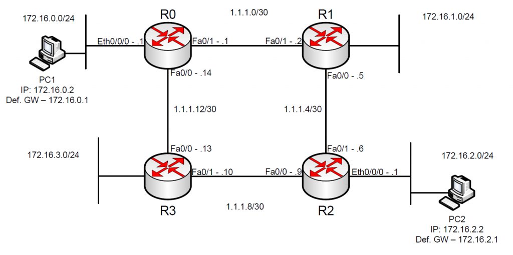
This small network is running OSPF on all links. No special configurations are used at the moment - all routers were simply configured to run OSPF on all links, and in one OSPF area. We will be exploring OSPF’s view of the network after convergence, and how it built the routing table on each router. I constructed this topology to show connectivity between two hosts - namely PC1 and PC2, and gain some visibility into how these routers have chosen to pass traffic between them.
Take a look at the output of the “show ip route” command, issued on R0:
R0#show ip route
.....
1.0.0.0/30 is subnetted, 4 subnets
 C    1.1.1.0 is directly connected, FastEthernet0/1
 O    1.1.1.4 [110/2] via 1.1.1.2, 00:10:04, FastEthernet0/1
 O    1.1.1.8 [110/2] via 1.1.1.13, 00:10:04, FastEthernet0/0
 C    1.1.1.12 is directly connected, FastEthernet0/0
 172.16.0.0/24 is subnetted, 4 subnets
 C    172.16.0.0 is directly connected, Ethernet0/0/0
 O    172.16.1.0 [110/11] via 1.1.1.2, 00:10:04, FastEthernet0/1
 O    172.16.2.0 [110/12] via 1.1.1.13, 00:09:24, FastEthernet0/0
                 [110/12] via 1.1.1.2, 00:09:24, FastEthernet0/1
 O    172.16.3.0 [110/11] via 1.1.1.13, 00:10:04, FastEthernet0/0
The first thing that should draw your attention are the words “directly connected”, represented by the letter C to the left. These are routes that were not distributed via OSPF, but are networks that are directly connected to the router. The router inherently knows of these networks, so there’s no need to hear about them from another router. Given our topology, there should always be exactly three of these, no matter which router we’re looking at.
The other routes are represented by an “O” to the left, which identifies them as routes received via an OSPF neighbor relationship. These are networks that are not directly connected to this router, and were announced by some other router on the network.
If there was a “rule of thumb” with regards to routing, it would be “The most specific route wins”. This means that the route with the longest subnet prefix that matches a given packet’s destination IP address will be used to route that packet. When there is a tie, there are other mechanisms that allow a route to be selected, such as administrative distance, and metric.
Notice that the routing table is broken up into two parts:
1.0.0.0/30 is subnetted, 4 subnets
......
172.16.0.0/24 is subnetted, 4 subnets
......
This is because routing tables look at these routes first in a classful way. For instance, 1.0.0.0 is in Class A address space, so a natural mask of /8 is assumed. Since all routes in this space are /30, the router lets us know that this space has been subnetted, and even gives us the number of subnets present in this space. The same can be said for the 172.16.0.0 routes, since the natural mask for this Class B address space is a /16. Since we’re using masks that are not “the norm” for these address spaces, it is letting us know that this address space has been subnetted.
Let’s look specifically at one of the routes, and we’ll break it down into it’s components so that we can properly define them:
O 172.16.1.0 [110/11] via 1.1.1.2, 00:10:04, FastEthernet0/1
This particular route represents how R0 should send packets to the LAN that’s directly connected to R1. The first component of this route is the “O”, indicating that this route was obtained via OSPF (There is a legend in the output of “show ip route” for these letters but I took it out for the purpose of this explanation).
Next, we see “172.16.1.0”. This is the remote network that the route represents.
Next, there’s a section that’s all too often overlooked. Within these brackets we see two numbers. First, the value 110 represents the administrative distance of this route. Administrative distance determines how trustworthy this route is. If there is a similar route but with a smaller administrative distance, it is used instead, because it is more “trustworthy”. The smaller the administrative distance, the more trustworthy the route. (It is hidden in the output shown above, but directly connected routes have an administrative distance of 0, which makes them the most trustworthy type of route.) The second number, 11, represents the metric for the given routing protocol. The metric varies from protocol to protocol, but OSPF is what we’re using, and the metric for OSPF is cost, which indicates the best quality path to use to forward packets. Cisco IOS derives this value primarily through bandwidth. (Other protocols, like RIP, use hop count as a metric. For neighboring routers, you’d see a metric value of 1.)
Next, we see “via 1.1.1.2”. This tells us that this route is available through the next hop router located at that IP Address, which happens to be R1. This is an important component of ip routing, as it identifies exactly where packets go when they match this route.
The next part says “00:10:04”. This is the length of time that this route has been present in the routing table. This particular route has been present for 10 minutes and 4 seconds. This is therefore also the length of time this route has existed without an update. If the route were removed and then re-added (if the cable was disconnected, for instance), this timer would begin again at 00:00:00.
Finally, we see an interface name, specifically, FastEthernet0/1. This indicates which interface is used to get to the next-hop address for this route. Looking at our topology diagram, we see that this interface is used to connect R0 to R1, so this is correct.
So, we arrive at our practical demonstration. We’d like to perform a ping from PC1 to PC2. Can you identify which route will be used to get there?
O    172.16.2.0 [110/12] via 1.1.1.13, 00:09:24, FastEthernet0/0
                [110/12] via 1.1.1.2, 00:09:24, FastEthernet0/1
Based on this specific route, the packets from PC1 will be sent to R0, then to either R1 or R3. We know this because these are the routers that use the next-hop addresses specified in the route. In addition, both the administrative distance values and the metrics are the same. This is because both routes were obtained through OSPF, and all links in question have the same cost.
These packets require one and only one route to get to the destination, so which one is used? Lets run a traceroute on PC1 to PC2 to and see which route this traffic takes:
PC1>tracert 172.16.2.2

Tracing route to 172.16.2.2 over a maximum of 30 hops:

  1   63 ms     63 ms     63 ms     172.16.0.1
  2   94 ms     94 ms     51 ms     1.1.1.13
  3   125 ms    125 ms    112 ms    1.1.1.9
  4   175 ms    188 ms    156 ms    172.16.2.2

Trace complete.

PC1>
So it looks like the first hop after R0 is 1.1.1.13, which is R3. So, we have our answer. Or do we? Lets run that trace again, with no changes to our routing configuration:
PC1>tracert 172.16.2.2

Tracing route to 172.16.2.2 over a maximum of 30 hops:

  1   47 ms     63 ms     49 ms     172.16.0.1
  2   94 ms     94 ms     94 ms     1.1.1.2
  3   109 ms    125 ms    93 ms     1.1.1.6
  4   187 ms    172 ms    156 ms    172.16.2.2

Trace complete.

PC1>
Wait a second! We now have a different next-hop after R0. Instead, the next hop is now R1.
The reason for this is that OSPF is performing automatic load balancing on this route. Since the two next-hops for the route to 172.16.2.0/24 from R0’s perspective were essentially tied, R0 is load balancing traffic between the two possible routes. This gets into a bit more advanced topics concerning OSPF, so I’ll save that for another day.
In the meantime, we’ve learned how a routing table works, and how routes are decided. In the event of a tie, there are certain measures, some manual, some automatic (as we’ve seen with OSPF) that can be used to break the tie.
For more on route selection on Cisco routers, see http://www.cisco.com/en/US/tech/tk365/technologies_tech_note09186a0080094823.shtml